linear sources.
Linear sources are the most known to us all, those with a step-down transformer, a diode bridge to move from continuous alternating pulsating and a filter capacitor to soften as much as possible those peaks of continuous pulsing.
An unregulated linear supply can have a multiple should or should, so you can have an output voltage or more, among them several such tensions could be all positive or all negative or mixed or symmetrical.
An example of a source with multiple outputs may be to those sources that are sold as universal have a switch to choose between 1.5, 3, 4.5, 6, 7.5, 9 and 12V are not the best quality but if is a source with multiple outputs, which achieve a transformer with multiple windings.
A Balanced source may be, for example with two windings where we get + / - 12V or 5V or 25V or whatever you want, usually used around circuits that need to process signals either signal processors, sound cards, audio amplifiers, etc. ..
and then we mixed sources are not symmetric and symmetric tension, an example is the source of PC, as this has +12 V,-12V, +5 V,-5V, +3.3 V, etc ...
Then allow circuits to be able to tell the difference between simple windings, multiple and mixed.
 now talk a little about the theory of these sources, which may be half wave, full wave two-diode full-wave or four diodes (diode bridge).
 As we know the main thing is the step-down transformer, this transformer how we will use in the mains at 50Hz has to be in resonance at this frequency, therefore we know all the coils and capacitors often respond in a coil, the frequency is inversely proportional to the inductance bone to the amount of turns , for example, more often less coil turns and more turns less frequently.
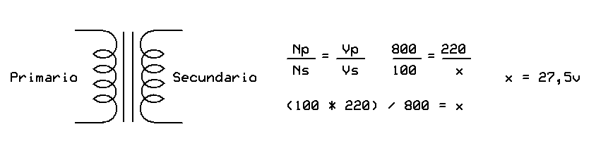
For 220V 50Hz transformer have approximately 800vueltas of primary to have a relationship detransformacion direct calculation is Np / Ns = Vp / Vs, which tells us that primary turns N on N turns of secondary voltage equals the primary on the secondary voltage, ie, if the primary we have N = 800 laps 220, and the secondary have N = 100 laps, we will have an output voltage of 220 V / 8 = 27.5 V. In this way returns are calculated on a transformer to calculate the tension that gives us. Another factor to consider is the diameter of copper, the bigger it is, the more current transformer thus bear the most consumed. From there comes a transformer 220 to 12 1A is much smaller than one of 220 to 12 8A, just for the copper diamtro.
The diode bridge, is nothing more than a series of diodes is a function of the frequency response, current and voltage. For example for a transformer 220 to 12 8A Didos have to use Si (silicon) of low frequency and more than 8A so as not to destroy and to respond well.
After this comes the capacitor, which is calculated by Ampere 1000uF thus source for this source of 8A would have to use a 8000uF capacitor for 12V, but as there is these values, we use a capacitor for 16V or 10000uF two for 16V 4700uF capacitors in parallel.
NOTE: capacitors in parallel add their capacity and the remaining series.
Here I leave a diagram of a 12V supply half wave, full wave other two diodes and a full wave with four diodes and their graphs to understand the signal delivered.

Now we know that we will proceed to the same sources but regulated by voltage regulators.
probably already know this but we will give you a little refresher, these same sources mentioned above can add voltage regulators whether positive, negative, stable or controlled.
We are going to talk about National Semiconductor regulators, the famous LM, first begin by positive regulators LM78XX series, where XX is the value that will take number based on the output voltage we need. For example we
LM7805, LM7806, LM7808, LM7809, LM7812, LM7815, LM7824 as the best known and the negative branch going to have the same values \u200b\u200bworse instead of LM78XX will LM79XX, we must bear in mind that although they are physically equal the connection is not the same.
 also have the option to use regulatory variables, such as the LM317 or LM337
 dare
 Below application circuit for a 5V source with 12 and another source with + / -12 and + / - another regulated 5V and 1.2V to 30V.
SMPS Power Sources type SMPS (Switching Mode Power Supply) As I said the word is a power supply switch mode. Are the sources that have the PC, DVD, TV, Etc. ..
First we should know that means switch where it comes from and how did we get here.
While certainly being imagined as a switch a switch, if so, where mark is a switch on or off, in our house 1 and 0. The transistors have a response curve which can work in court and saturation (in addition to working in dynamic mode in the center of the point Q "for amplifiers and analog signal handling), the court and the saturation of a transistor is what allows the transistor binary switch on and off without going through intermediate states.
Imagine a bobbin, the transistor behaves like we have a flow of water going from collector to emitter or collector-emitter (depending on the conflagration) and I shall have the knob, close or graduate flow water, this would be the base of the transistor.
In our case it would be a tap that I shall at all (saturated) or fully closed (short).
Once we realize that the transistor can work as a key in cutting and clipping., Hence the switch in the source word, and because we say it is a power switch instead of a line source as we saw before, well now we find another difference to the line source, we know that both have a transformer but has a large transformer and the other one much smaller. Going
us a little inductors, above we said that more inductance (more turns of coil) less frequently, more often lower inductance.
If, for a 50Hz transformer we are using 800 turns of the primary, then for a 50Hz transformer more than you'll use fewer turns of the primary, and if the transformer works at 50kHz (50000Hz) will be far fewer turns, hence here comes the transformer but boy, whether it is the same processor in the line source but to elevate the frequency can reduce the number of turns and therefore its size and weight.
Now we know it is smaller the source SMPS transformer, there is the issue that we must generate these 50000Hz as the home mains 50Hz only gives us, for this is the name Switching, this is where the power transistor turns and off the transformer primary 50kHz, osea processors running at 50000Hz have to make it go at that frequency but does not respond, then we have no choice but to do this frequency range or as they say in the jargon, do switch, to this we need an oscillator that command a transistor (or several) which in turn make the transformer 50000Hz range, once we have this rocking the processor is already running, and only remains secondary to the common source, diodes, capacitors, regulators etc ... only now we're not in 50Hz 50000Hz but we are as the diodes are not any but must be ultra fast to respond to this frequency. we now have the power to walk, but this source and has an oscillator circuit for the primary, and the circuit is continuous, we need continuous supply voltage to power the primary, here is where the direct source of 220Vac, probably will have seen sources that direct PC the 220Vac is a bridge rectifier, a filter and a 400uF capacitor as for 400V, or something similar. Hence 330Vcc out which is the stress that goes to switches transistor processor. With this in mind we've got some control oscillator circuits of the source, apart from rock, control the voltage that reaches the base of the transistor, so you do not have power surges or low voltage, this happens when there is but climbs 220Vac tension or low, all that is offset control transistor letting more or less stress to their base and controlling the output voltage of the transformer. Insurance also saw an opto-coupler there, opto-coupler that serves two purposes, first to find out how often this actually swinging l transformer, and if you are able to self adjust frequency and the second is knowing that the voltage Reference is fine, if you have more or less the line to know that the transformer secondary is delivering what it has to deliver, so you put the opto-coupler output transformer to the integrated control.
Obviously the secondary of this transformer as a source line can have multiple secondary windings or more shots in the winding, hence we get various stresses such as a PC source.
now stop a block diagram.
 An example of a driver for these sources can be the SG3524 integrated circuit that has the following characteristics:
 • Control of PWM power circuit
This ensures that the transistor switches at the transformer will, this optimizing the signal for the lowest energy can get a good stability of oscillation.
• push-pull outputs
This tells us that we can connect the output transistors switch (to command the processor and do vary) in Push-Pull conflagration (a transistor to command the floor for the positive and negative)
• 1% maximum temperature variation
allows us to maintain stability even in locations with high temperatures.
• Total supply current less than 10mA
integrated low power consumption function of the source.
• Operation beyond 100kHz
We can handle frequencies that are in the order of 100000Hz (use transforamdores more kids with fewer turns of copper)
leave two circuits here application from its datasheet, the first is a common source to get from 26Vcc SMPS 5V 5A with the integrated SG3524.
Here
 leave another circuit from the datasheet, but this is a source for Step-UP, I mean to raise the stress such as the powers of self, that apart from rising to 12V + /-50V, etc. . This case brings
 5V to + /-15V, does not fall too much current, in fact less than 100mA so only serves to logic circuits, but can be modified for more power.

0 comments:
Post a Comment