Saturday, December 25, 2010

How To Treat Gall Bladder Polypse

Motion Sensor / Ultrasonic Proximity

The circuit presented is to study Ultrasonic sensors and to analyze and improve the circuit and that this can be improved further.
The first stage consists of an amplifier for the ultrasound receiver, the output of this is entered into the second stage of amplification, the output of this second stage has two functions, to deliver the signal to be analyzed and to feed the transmitter ultrasound, since this transmitter is powered from the output of the receiver, we can say that ultrasound is a feedback, this is what to discard the use of oscillators and other circuits.
On the other hand the output of this second stage of amplification is sent to an AM detector, while the non-germanium diodes (can be improve), the circuit sends enough voltage level to be able to excite these diodes, and finally to the output of this detector is an amplifier with an LED to verify the circuit performance.
It is obvious that what develops in this way because it is an improved circuit and simplifiacrlo widely as possible, but could add operational amplifier as a comparator to be more stable output or schmitt trigger logic circuits simply to neutralize the chimes wrong.
The circuit is next, and append the link to youtube of it working.

Link to youtube
http://www.youtube.com/watch?v=pGSvVraiot4

Saturday, December 11, 2010

Can You Get A Brazilian Wax If You Have Hemrroids


This circuit was designed with the purpose of feeding a particular circuit from the USB port, of course feed the circuit did not require much current, it was utilized by the voltage doubler and no other inducers . The circuit is very basic, consists of an oscillator based on the timer 555, and a voltage doubler designed based on the multiplier voltage diodes and capacitors. the same due to its low frequency requires high-capacity capacitors also going to provide a current of about 15mA, of course you can change, but the 555 should be replaced by a two-transistor oscillator power or a power oscillator and capacitors should be changed. While this circuit doubles the voltage bone the doubles, it is possible to triple or multiply by higher values, just keep adding stages of multiplication (Didos / capacitors). The circuit is as follows.


Thursday, December 9, 2010

Garrison Lock Combination How To

eternal legislava bureaucracy denying homosexuals in the military.

are senior commanders of the U.S. Armed Forces against the special Senate Commission in the case of the law prohibiting gays and lesbians in their ranks .

In a nation considered one of the freest countries on Earth, with a constitution guaranteeing freedom, happiness and human rights for all citizens, legislators insist on ignoring the provisions of the Charter, prohibiting the right of those with different sexual orientation to serve in the ranks of its armed forces, an organization that really desperately needs individuals who will kill and die in the wars more useless and frustrating, inherited a government is represented today by the same individuals who created this worthless legislation in 1993, love of their police in the Korean peninsula and elsewhere.

The government of President Obama wants to end this side against their coinciudadanos, whatever their denomination or sexual situation but do not let a small group of Republicans and conservative Democrat, The Armed Forces Command also supports his term; The Minister of Defense and a huge population notes with disappointment as lawmakers make and break of this social phenomenon, not even stopping a moment to consider telling polls and surveys clearly it's time to let this smallness and the absurd probability that the homosexual is an epidemic spreading to every soldier.
It is a matter of acceptance by both concerned!
In our opinion and that of Amnesty International is simply unacceptable discrimination wrought by the eternal politicking of Washington, conservative politicians with the sole intention of voting against anything that comes, proposed by the government accepts and Obama.
-57/40- The Senate vote was forced by the Democratic majority Senate according to their Leader, Nevada Senator Harry Reid, for being tired of the political game of Republicans and because discrimination , he told Our correspondent on Capitol Hill, July Perezcotapo ...
--- " has never served or worked well in our country ."
go another way.
is quite possible, however, that this anti-gay law in the armed forces go to the federal courts and the High Command sought his term in the ordinary courts to terminate it once and for all.
not talking about homosexuality here trying to belong to American society as such, or acceptance of principles only, but in open public exclusion on the one hand, and to ignore the basis upon which was created for people in this country in 1776, on the other. Cynicism
legislature.
incredible thing about this position Sendor discriminatory Republicans is that in April of 2010, according to Amnesty International, these same legislators overwhelmingly passed and approved a resolution "requesting Parliament of Uganda to reject every proposition against Gay and any law to discriminate against individuals solely because of their sexual orientacon "laughable considering that in his own country think and do exactly the opposite.
We have other interesting headlines for you and if you want to know who we are and what we do ,.....
Click here.

Tuesday, August 31, 2010

Maytag Performa Pav2300aww

Voltage Doubler Power Microcontrollers

linear sources.
Linear sources are the most known to us all, those with a step-down transformer, a diode bridge to move from continuous alternating pulsating and a filter capacitor to soften as much as possible those peaks of continuous pulsing.
An unregulated linear supply can have a multiple should or should, so you can have an output voltage or more, among them several such tensions could be all positive or all negative or mixed or symmetrical.
An example of a source with multiple outputs may be to those sources that are sold as universal have a switch to choose between 1.5, 3, 4.5, 6, 7.5, 9 and 12V are not the best quality but if is a source with multiple outputs, which achieve a transformer with multiple windings.
A Balanced source may be, for example with two windings where we get + / - 12V or 5V or 25V or whatever you want, usually used around circuits that need to process signals either signal processors, sound cards, audio amplifiers, etc. ..
and then we mixed sources are not symmetric and symmetric tension, an example is the source of PC, as this has +12 V,-12V, +5 V,-5V, +3.3 V, etc ...
Then allow circuits to be able to tell the difference between simple windings, multiple and mixed.

now talk a little about the theory of these sources, which may be half wave, full wave two-diode full-wave or four diodes (diode bridge).
As we know the main thing is the step-down transformer, this transformer how we will use in the mains at 50Hz has to be in resonance at this frequency, therefore we know all the coils and capacitors often respond in a coil, the frequency is inversely proportional to the inductance bone to the amount of turns , for example, more often less coil turns and more turns less frequently.
For 220V 50Hz transformer have approximately 800vueltas of primary to have a relationship detransformacion direct calculation is Np / Ns = Vp / Vs, which tells us that primary turns N on N turns of secondary voltage equals the primary on the secondary voltage, ie, if the primary we have N = 800 laps 220, and the secondary have N = 100 laps, we will have an output voltage of 220 V / 8 = 27.5 V. In this way returns are calculated on a transformer to calculate the tension that gives us. Another factor to consider is the diameter of copper, the bigger it is, the more current transformer thus bear the most consumed. From there comes a transformer 220 to 12 1A is much smaller than one of 220 to 12 8A, just for the copper diamtro.


The diode bridge, is nothing more than a series of diodes is a function of the frequency response, current and voltage. For example for a transformer 220 to 12 8A Didos have to use Si (silicon) of low frequency and more than 8A so as not to destroy and to respond well.

After this comes the capacitor, which is calculated by Ampere 1000uF thus source for this source of 8A would have to use a 8000uF capacitor for 12V, but as there is these values, we use a capacitor for 16V or 10000uF two for 16V 4700uF capacitors in parallel.
NOTE: capacitors in parallel add their capacity and the remaining series.

Here I leave a diagram of a 12V supply half wave, full wave other two diodes and a full wave with four diodes and their graphs to understand the signal delivered.


Now we know that we will proceed to the same sources but regulated by voltage regulators.
probably already know this but we will give you a little refresher, these same sources mentioned above can add voltage regulators whether positive, negative, stable or controlled.
We are going to talk about National Semiconductor regulators, the famous LM, first begin by positive regulators LM78XX series, where XX is the value that will take number based on the output voltage we need. For example we
LM7805, LM7806, LM7808, LM7809, LM7812, LM7815, LM7824 as the best known and the negative branch going to have the same values \u200b\u200bworse instead of LM78XX will LM79XX, we must bear in mind that although they are physically equal the connection is not the same.

also have the option to use regulatory variables, such as the LM317 or LM337

dare Below application circuit for a 5V source with 12 and another source with + / -12 and + / - another regulated 5V and 1.2V to 30V.


SMPS Power Sources type SMPS (Switching Mode Power Supply) As I said the word is a power supply switch mode. Are the sources that have the PC, DVD, TV, Etc. ..
First we should know that means switch where it comes from and how did we get here.
While certainly being imagined as a switch a switch, if so, where mark is a switch on or off, in our house 1 and 0. The transistors have a response curve which can work in court and saturation (in addition to working in dynamic mode in the center of the point Q "for amplifiers and analog signal handling), the court and the saturation of a transistor is what allows the transistor binary switch on and off without going through intermediate states.
Imagine a bobbin, the transistor behaves like we have a flow of water going from collector to emitter or collector-emitter (depending on the conflagration) and I shall have the knob, close or graduate flow water, this would be the base of the transistor.
In our case it would be a tap that I shall at all (saturated) or fully closed (short).
Once we realize that the transistor can work as a key in cutting and clipping., Hence the switch in the source word, and because we say it is a power switch instead of a line source as we saw before, well now we find another difference to the line source, we know that both have a transformer but has a large transformer and the other one much smaller. Going
us a little inductors, above we said that more inductance (more turns of coil) less frequently, more often lower inductance.
If, for a 50Hz transformer we are using 800 turns of the primary, then for a 50Hz transformer more than you'll use fewer turns of the primary, and if the transformer works at 50kHz (50000Hz) will be far fewer turns, hence here comes the transformer but boy, whether it is the same processor in the line source but to elevate the frequency can reduce the number of turns and therefore its size and weight.
Now we know it is smaller the source SMPS transformer, there is the issue that we must generate these 50000Hz as the home mains 50Hz only gives us, for this is the name Switching, this is where the power transistor turns and off the transformer primary 50kHz, osea processors running at 50000Hz have to make it go at that frequency but does not respond, then we have no choice but to do this frequency range or as they say in the jargon, do switch, to this we need an oscillator that command a transistor (or several) which in turn make the transformer 50000Hz range, once we have this rocking the processor is already running, and only remains secondary to the common source, diodes, capacitors, regulators etc ... only now we're not in 50Hz 50000Hz but we are as the diodes are not any but must be ultra fast to respond to this frequency. we now have the power to walk, but this source and has an oscillator circuit for the primary, and the circuit is continuous, we need continuous supply voltage to power the primary, here is where the direct source of 220Vac, probably will have seen sources that direct PC the 220Vac is a bridge rectifier, a filter and a 400uF capacitor as for 400V, or something similar. Hence 330Vcc out which is the stress that goes to switches transistor processor. With this in mind we've got some control oscillator circuits of the source, apart from rock, control the voltage that reaches the base of the transistor, so you do not have power surges or low voltage, this happens when there is but climbs 220Vac tension or low, all that is offset control transistor letting more or less stress to their base and controlling the output voltage of the transformer. Insurance also saw an opto-coupler there, opto-coupler that serves two purposes, first to find out how often this actually swinging l transformer, and if you are able to self adjust frequency and the second is knowing that the voltage Reference is fine, if you have more or less the line to know that the transformer secondary is delivering what it has to deliver, so you put the opto-coupler output transformer to the integrated control.
Obviously the secondary of this transformer as a source line can have multiple secondary windings or more shots in the winding, hence we get various stresses such as a PC source.
now stop a block diagram.

An example of a driver for these sources can be the SG3524 integrated circuit that has the following characteristics:
• Control of PWM power circuit
This ensures that the transistor switches at the transformer will, this optimizing the signal for the lowest energy can get a good stability of oscillation.
• push-pull outputs
This tells us that we can connect the output transistors switch (to command the processor and do vary) in Push-Pull conflagration (a transistor to command the floor for the positive and negative)
• 1% maximum temperature variation
allows us to maintain stability even in locations with high temperatures.
• Total supply current less than 10mA
integrated low power consumption function of the source.
• Operation beyond 100kHz
We can handle frequencies that are in the order of 100000Hz (use transforamdores more kids with fewer turns of copper)
leave two circuits here application from its datasheet, the first is a common source to get from 26Vcc SMPS 5V 5A with the integrated SG3524.

Here leave another circuit from the datasheet, but this is a source for Step-UP, I mean to raise the stress such as the powers of self, that apart from rising to 12V + /-50V, etc. . This case brings
5V to + /-15V, does not fall too much current, in fact less than 100mA so only serves to logic circuits, but can be modified for more power.

Coil Cleaning Solution Homemade


Audio Audio is a topic that covers many areas, from knowing how to do a volume control, to assemble a full team. in this case we will deal with all issues as far as conventional usable and accessible.
know how to start with their connectors are called, How to mount a volume control, and audio mixing, and audio display, such as discrimination or control ovbiamente as spectrum and amplify its signal and play it on speakers.
The idea of \u200b\u200bthese books is more than anything to have a practical idea, which can be applied since it does not touch issues in which to carry out the project to be expensive or very time consuming. Connectors


will detail the types of connectors for audio inputs and outputs, and are of low signal or power.
TRS TRS is called as stands for tip, ring and sleeve or Castilian tip, ring and handle, refers to the connectors that are three ways, as they have a point, a way, a ring as another way and the handle usually use it as it is the gnd via Webmail, come in three sizes that are indexed both with 2, 3 or 4-way, the measures are 2.5mm, 3.5mm and 6.3mm. below will show a picture of these connectors in 3 ways as it is normal for audio.


Cannon XLR-3 this connector is very common in and microphone inputs that despite having 3-way audio is sent only in mono. this is so because a pin is used to gnd, and the other two pins are used to send mono audio channel, but with a difference, a pin will send the mono audio to 0 and the other going to send the same signal but inverted 180 this is so because as used in professional audio cables usually very long and tickets are near high wattage lamps or audio equipment much power, it is not target the electrical noise in the cable so it sends the same signal twice only the second is inverted, so when entering the input signal to balanced mic-circuit operational amplifier, is entering the two signals in a differential amp configuration oper in this way it does is take the difference signal between the two signals out of phase and this difference is removed with this amp oper, is just noise, so it's used This pro audio interface called balanced input. also be used for audio line instead of microphone and can come in another connector such as the 6.3-mm TRS Jack.


these RCA connectors are most common in audio, is a standard for what is line-in in some countries is 200mVpp (0.2 V peak to peak) and in other countries is 1Vpp , but more often is found in 200mVpp.
is only used for audio input tambein but can be used to extract audio with the same signal level as it would 200mVpp bone in or out of line usually come in red and white for two channels.

Speakon connector this may not be very common in home PCs, but is very common in pro audio, power and speakers or high-power connector 4 is a bias that supports up to 20A and it is used in power outputs audio or power speakers.

Terminals in terminals and know well are those that come in amplifiers and speakers household may be either rotary or screw-type connector can be fast as those with the button.


Volume Control The volume control is a fundamental PIESA a sound, is what allows us to control the audio level that we want listen. There are many types of volume controls that can be in common or electronic potentiometers for DC (direct current),
Following is the basic connection of a single volume control, but the stereo is the same as the two-channel stereo audio equal. Note that one pin of the potentiometer will go to gnd, and the center will use it to the amplifier and the anger right at the entrance, this is so because we are used to increase the volume by turning the potentiometer clockwise this means right to say that approaching the entrance to the amplifier input signal and if you lower the volume queresmos turn left therefore approached the amplifier input to gnd, why is the order of the pins, the amplifier must always be in the middle because if we do not want volume, we do not want any ambient noise goal then put the amplifier input to gnd.


Mixers mixers as it says the word is to mix the audio, I mean putting aside the work of a DJ, this could serve to have multiple entries for example, connect a Diskma, mp3 player , a PC, etc. .. and each with its own volume control that can be independent or not, and all these audio sources to a single amplifier, with that saved the theme of walking plugging and unplugging. Sure you can use an input selector also where we select only the entry you want a multiple switch. But also we have for example 2 audio is not handle the volume of each (as in a mixer) but as the volume controls from the device, such volmuen control the pc or the mp3. An example of this is the Edifier speakers that come with more than one ticket so we can keep it plugged in more than one audio source.


VU meters VU meters are instruments for measuring the level of audio you are listening, may come in different forms and scales, for example could be a CCFT tube, with LEDs, with instrument needle, etc. .. and scale of measurement can be only 1 to 10 as also the power level eg 0.5 W to 50W, or for example in dB usually between-26dB to +6 dB.
There are several ways to connect a VU meter and a VU meter, for example in a connection issue may be connected to the amplifier input signal, the power output of the amplifier, or in some cases (most are approaching a audioritmo can connect a microphone to take the ambient sound). Also they can be found in different models, such as with integrated VU meters, with integrated operational amplifier, transistor ...
Below will show some practical circuits already in use for connecting to a VU meter audio input of an amplifier, which will put the VU meters go to the audio power output, because these were common in their output amplifiers were Class AB speaker terminal bone to the output and the other to gnd, but as today is fashionable integrated amplifier in the two H-bone are amplified speaker terminals up and connected to the integrated, and the VU meter does not work very well and we have complexes with the circuit, which is not necessary and can connect to signal input. Particularly
I'll take the 5 led, as it has much more gain than ten and runs excellent.


tone control filtering filtering and control
tone or equalizer, is a part that might help the good performance of our speaker, and also to adjust to taste or equalize the wave of our song we are listening.
Usually in vintage amplifiers and home control was done in low, medium and high, also could be found only with Low and High control, and as you know, and there also existed the equalizer bands such as 10 or 15 or 20 or 25, good for which the manufacturer has put forward. All this also is done today, in antiquity only comment today because finding an audio amplifier that is only audio amplifier is complicated. Because they are just amplficadores are usually for standard Hi-End are bone talking without tone control amplifiers or anything just the volume control to be as flat as possible the amplification and thus can not be interfering with the audio signal, and these amplifiers costing up to 5000 dollars. So I say that there are no amplifiers, only sold as symptomatic amplifiers amplifier that is radio, and come with 10 audio channels, 30 tickets for all home appliances, remote control has 80 buttons and if an amp ... but hey that too around 1000 dollars. We are forced to buy cheap audio, the marrow or home theater speaker 2.0 Edifier, or if we spend more we have to go buy a bowling power of 800 pesos but has only volume control and not because they're Hi-End .. but because they are not interested in adding another control and that are always connected to equalizers and sound consoles or any cross over. Resuming
a bit, I'll explain what they are tone controls for DC (direct current), analog tone controls with operational amplifier (the most used).
tone control by CC: This is like the name says with a tone control current, which means this, that control how to control osseous each of the tones (usually only bring sharp and record) is through continuous tension, the difference between analog tone control is that the tone potentiometer handles esecontrol audio signal directly, and this control for DC only handles continuous tension that enters the electronically integrated and handled in audio level. Some circuits that allow this are the TDA1524, the KA2107, the LM1036. No upload circuits because you really do not work very well unless you are highly modified for this purpose and thus are also making noises so only upload circuits that work well.

analog tone control: This tone control is based on the frequency filtered by capacitors, for example knowing that the audio range from 20 to 20000Hz could say that for a tone control osseous bands you record three midrange and high We could divide this bandwidth into three (the width Bandwidth is the amount of frequency that falls within the limits of 20 to 20000Hz 19980Hz bone) good considering this then dividing into three we know the bandwidth for each of the bands bone to save, mid and treble from there with a simple filter capacitors can be cut as often as we want, this is because the capacitor responds to a certain frequency, bone for detereminada comprotar often be as low resistance and another frequency as a high resistance (ie is called capacitive reactance and Xc note the acronym) good suppose we calculate a capacitor to miss only the low, we will want to miss are the frequencies of 500Hz and down that are above the 500 who did not miss, in this case behave as a high resistance for frequencies of 500 up and a low resistance for frequencies below 500 by then you will want to miss that. Same for the mids and treble. So now would be a passive tone control and grasping the audio signal and removes what you do not want, but the idea is to increase what you want is, that you store or give more acute over (for active tone control two bias) to appear this operational amplifiers, this is what will make the op amp is just amplifying what was filtered by the filter capacitors, the rest will be played directly, note that the entry audio through a resistenicas goes to the amplifier output thus the audio signal travels as it is not be modified (attenuated only slightly) and the signal entering the amplifier to be amplified is coming out of the potentiometers, We can therefore say that only amplify what we choose with the potentiometers, such as audio signal coming saldra unmodified record them but if we increase these prints will go to operational amplifier input and added to the signal Direct taxes thus will output the same signal as before but with more save, from there comes the word active, bone is an active tone control because the bands are amplified to control is enhanced sound, also said in some amplifiers that have enhanced recording or treble boost, etc ...

headphone amplifier
As I said the word is a headphone amplifier, which, although I can ask to get to like it, some people pay up to $ 1000 for one, sure that he who pays is because you are buying a headphone amplficador of high quality, but also there are consoles that are just bone headphones that have multiple inputs and multiple outputs for headphones and so we can distribute multiple audio headphones. Can also be very commonly used with high preestaciones headphones, such as a common headset such as a $ 50 sony comes with an impedance of 50 to 100 ohms and a high preestaciones headset such as a sennheiser or bose or shure, comes with an impedance of 300 ohms, because they change their impedance, we know from Ohm's law that if we maintain such 5V 50ohm load will have a current of 100mA but if we change the load resistance of 300ohms going to have a current of 16mA in this way to lower the current low audio distortion therefore gives us more sound quality, so we have more pro headphones impedance, but low current passing hence low power and that is when we say "when I was the cheap headphones sounded stronger than with expensive headphones" that's because to lower the low current power pro headphones then do not listen so hard, but it appears the issue headphone amplifier to power supply is low.
The amplifier is common as any other single that tratarce low power less than 1W is not necessary to use transistors or large heat sinks or sources, if necessary symmetric feeding source such as a + /-12Vdc and 500mA, with So we can feed a normal operational amplifier preestaciones widely used as the NJM4556 enconsolas sound for headphone output (used DJ headphones that are usually pro) clear that we can use some better integrated including some of the OPA family of Texas Instrument but these are harder to get and rather more expensive, therefore we will only use the NJM4556, keep in mind that the sound quality of a team not only is the integrated use, but the entire circuit if nothing Sirba use the best integrated if after you do the circuit on a defective, failed components without calculating them, and a poorly filtered power, so I say that it is all about. But however this works very well integrated.

power amplifiers
This topic is trying to understand a little more common classes used in audio, and the most basic circuit assembly you may get disappointed.
Classes most used audio amplifier are ClaseAB and ClaseH but there are also others such as ClaseA but the low efficiency of power that some people use only because they also have more quality but with a good class AB DIN45500 achieves the standard (the Hi-Fi standard.)
Hi-Fi The rule says that to meet her need at least two channels must be osea stereo amp, then we need more than 5Wrms per channel and a maximum of 0.1% total harmonic distortion (THD).
cals AB The TDA2616 is a single bone is amplified speaker terminal.
This is + /-10Wrm per channel with 0.15% maximum THD. This IC is used by its Balfe 2.0 Edifier R1000. You have protection against temperatures. The power supply can be simple or symmetrical to be simple is to add a capacitor in series with each output that complies with the funete symmetric function, the name of this capacitor is Bootstrap.


The TDA8563Q TDA1557Q and has both the same circuit as the only difference is that one is 22W per channel and the other of 40W per channel RMS clear that the first does not pass the 15W and the second does not pass the 25W but also are a good choice for ease of circuit, not lleba almost no external components. These devices are ClaseH or Bridge, the two temrinales bone are amplified speaker, as if tubiese two class AB amplifiers for each speaker, this gain in power, and source because the diet is simple and in this case is 12V therefore it is very practical for us.


The TDA1562 is class H is integrated mono but the interesting thing is that this is a source of tension inside lift "StepUp" that s used to be connected to 12VDC power clear that sources tend to spend enough lift more than they deliver, which is why this chip consumes about 5A, but deliver us from 50Wrms 12V, the circuit is relatively simple and quite good for almientar a subwoofer.


Speaker
This is a fundamental part of a sound, I would say that is 80% of the sound quality of a team, because if the box is not check so not sound calculated to 100% sun, in fact it You put the speakers are expensive because they are designed for the speaker to lead and not for any speaker, and I do not speak but speak sized speaker itself, I mean if we design a box for a speaker jbl 10 "just enter this and she could not size but because of the resonance frequency and other factors that make the tune of the box, I mean the box is a resonant element such as an antenna or a radio circuit, so we should not minimize the importance, for example if a badly tuned radio circuit grasp another radio frequency that does not interest us, that is, no box exprecion operating at its best, so I insist on the calculation of the speaker, leave a box below for the calculation of this, for acoustic reflex or closed boxes.

Riker Island Visiting Rules


NOTE: The programs in this tutorial are on the following link.

http://www.mediafire.com/?ydb5y3b6e3ljutg


While I will not give complex examples and I will use 100% of the micro, I will address this issue in function to a microcontroller (MCU) PIC family from Microchip

company. Microcontroller 
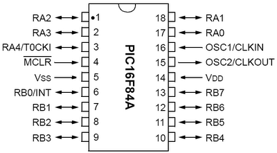
study the PIC16F84A PIC16F84A as it is the most common more accessible and easier to set record after its simplistic and configurations. Of course there are with more or fewer pins, with more or less preestaciones and different prices, but to start is the most estable.Descripción
PIC16F84A microcontroller (not go into details very deep for the mere echo of the guide serves all the public.)
a. 35 instructions. B.
External clock can be in the RC (RC-circuit) or XT with a glass of up to 4MHz (in default mode). C.
Flash memory of 1024 14-bit address word (here anger the program.) D.
64bytes Ram memory (data will be used to host variables values \u200b\u200bin the program). E.
64bytes EEPROM (to accommodate data we want to go away after rebooting the MCU). F.
8bit ALU (ALU is the arithmetic and logic unit, which is responsible for numerical operations). G.
Interruptions by INT/RB0 pin on the TMR0 timer, EEPROM for OVERFLOW and the state change on pins RB4 to RB7.
h. 1000000 to read and write cycles for EEPROM, and data retention for 40 years. I.
13-pin input and output to the outside. J.
Two ports E / S PORTA and PORTB bit 8bit 5. K.
A counter / timer TMR0 8bit call.
l. Electrical Characteristics: Temp -55 ° C to +125 ° C. 5V supply voltage. Maximum current
PORTA 50mA. 100mA maximum current of PORTB.

Principles assembly
In this guide we will learn what the assembler or Assembler language, in order to understand the logic that owns and eventually develop some simple programs.
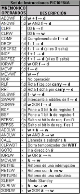
Each microcontroller has its different instruction set, the difference is in the manufacturer, I mean the set of instructions of a microcontroller of the mark Freescale (Motorola) "MC" is not equal to that of AVR (Atmel) "AT" or the Microchip "PIC" microcontrollers that we will see in this guide are of the firm Microchip and chose this particular because it has more kid instruction set of all (only 35 instructions for the line of 8bit). Then show you a picture with the instructions of the PIC.

Once we consider the instructions the pic driving, we must bear in mind that all of those pin that has thus are bidirectional input / output, and supporting clock rates and other settings should configured so that the microcontroller can know what we want to do and how we do it.
First on the agenda we have to tell the compiler that we want to use micro and the library where it will take instructions from the pic, this will write the first two lines program, leaving a space tab:

LIST P = 16F84A INCLUDE

To do this in the header of the program will write a series of characters indicating the type of watch that we will use if we are to use the watchdog (we know when the program crashes), protection code, and for example the delay that are behind the power so as not to generate a voltage spike that causes erratic shots.
that line would be:

__CONFIG _CP_OFF \u200b\u200b& _WDT_OFF & _PWRTE_ON & _XT_OSC


will then variables used with the EQU instruction means Equal or more, here was the hex address 30 and 31 only because I thought that but to refer to a memory point. is only for defining variables. there are other ways but they are more Abansa.


PEPA PEPE EQU EQU 0x30 0x31


After that we started the program, we must tell the micro to get started there, for it we're going to put the instruction:

ORG 0


This instruction tells us that the orgy of the program (ORG) is in the zero position memory (0) also can be placed in hexadecimal would 0x00, or other bases but the most common are those dos.Seguido of this instruction must configure the ports of the microphone.

bsf STATUS, RP0 clrf TRISB


clrf TRISA bcf STATUS, RP0


Here are three new instructions, the names of the two ports and the status that you will configure the microphone. Serious
instruction (BSF) means BitSetF this means that will setear (set to 1) bit of F (F is the value of the variable, in this case the variable is RP0, which is housed in a set variable called STATUS) RP0 will therefore be 1. STATUS has 8 bits where the RP0 bit is equivalent to number 5 graphically serious bone STATUS = 00001000.
then displays the instruction (CLRF) f this is clear, I mean delete the contents of f, but technically it reset. in this case will set TRISB (all its contents) to zero, as is the registration TRISB PORTB pin bone the integrated 8 port b, that if they are to 1 are inputs and 0 are outputs. in this case to say that deleting all the 8 bit TRISB to zero, bone
TRISB = 00000000, thus will all outputs. if she wanted would have to be input qeu be 11111111 or 11001100 can be mixed bone for example. CLRF instruction but no longer serve us because that just reset all variable. Ahohra
repeats the same but with TRIS PORTA bone registration that also puts zeros, hence also are outputs. Echo
Once this configuration appears STATUS, RP0 but with the instruction (BCF) which is BitClearF, bone (set to 0), now RP0 = 0 and STATUS = 00000000. with this we say we left the config, bone fijencen who first entered the settings, then configure and then left the configuration.
Now we started the program itself, which in our case will turn on LEDs to output port B, for this we will write:

modded
MOVLW b'01010101 'MOVWF PORTB GOTO
modded


Note that there are three directions, MOVLW, MOVWF and is moving GOTO.MOVLW the literal to W (where W is the RAM), W MOVWF is to move (so which moved earlier) F it was like we had said before the bit of the record in this case we refermios to PORTB and GOTO to last is "go."
then read this, first get a modded in the first line, this is a label that can have any name, refers to a point in the program. then a space appears MOVLW tabulation and then another tabulation of space appears b'01010101 'move this line says W the literal, the literal is b'01010101' which means the letter b to speak in binary (could be h hex, d for decimal, or octal, etc. ..) but because we Vinaria is more visible LED to be lit is the one with the 1 and it will be off is the one with 0, then will move to W 01010101 (which was the ram).
in the next row with a space and a tabulation tabulation MOVWF appears more and appears PORTB, here you are moving the contents of W to PORTB, remember that before he moved to W 01010101, so will move it to PORTB PORTB now is 01010101, as referred PORTB pic port (physical port "paws") the LEDs will be there on or stay apagadaos according to the binary number. Finally
tabulation shown by the GOTO and another tabulation the Modder, this means that going to jump modded label that was set up, which means that the program enters bone LOOP cyclically makes this all the time.
to terminate the program now need to tell, and it ends ponermos instruction:

END

Here temrino all, what remains is to compile this program with the Microchip MPASM (it's free and download page) and this will generate a series of files which are files of records, logs, comments, and we are interested in the *. HEX which is the code to be read in the pic, well this last file it will create if the program has no errors, but does not believe and should be corrected the codigo.Una Once we have this file just have to save the pic and for that we can use any program with any interface such as ICPROG (free) and the JDM programmer for serial port. only remains to record the pic and ready to connect the LEDs, glass and feed it 5V.

program:

;*************** endend PROGRAM LED BY THE PORT B \u200b\u200b**************** ****** ; ** Powered by modded , spaces between instructions and literals are made with tabs, not spaces. and the comments can go after a point and coma. LIST P = 16F84A INCLUDE __CONFIG _CP_OFF \u200b\u200b& _WDT_OFF & _PWRTE_ON & _XT_OSC PEPE EQU 0x30; Declaration of variable PEPE PEPA EQU 0x31; Statement of PEPA variable ORG 0; Source program in the zero position

bsf STATUS, RP0; The entrance to the configuration ports, putting a bit RP0 of STATUS clrf TRISB; It resets the TRISB register, this, way
transformed into outputs clrf TRISA; It resets the TRISA register of this, as they become
outputs bcf STATUS, RP0; Exit the configuration of ports by resetting the bit RP0 of STATUS modded, Label modded
MOVLW b'01010101 '; Moves 01010101 to
W MOVWF PORTB; Move the contents of W (01010101) to PORTB
modded GOTO, (Display is in the output)
; Jump to the label modded END; End

program
The circuit would be:


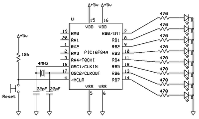
Now using the same circuit we get on and off at a speed visible.

;*************** Endend PROGRAM LED BY THE PORT B \u200b\u200bFLASHING **********************
; ** Powered by modded ; To attain that are flashing you must create a delay, we know that the micro is running to
; 4MHz (every instruction consumes 4 cycles hence the actual speed is 1MHz) then we would have to
down, speed it to see an LED turn on and off at 1MHz is ungodly, then to be vicible eg every 0.5 s
, we do a delay, I mean we do wasting time micro, as we accomplish this by making the micro pass, for a certain number of times instruction and then continue with the program, the number of times you go through that
; instruction determines the time to lose, hence the delay.

LIST P = 16F84A
INCLUDE

__CONFIG _CP_OFF \u200b\u200b& _WDT_OFF & _PWRTE_ON & _XT_OSC

PEPE EQU 0x30; Declaration of variable PEPA PEPE
EQU 0x31; Statement of PEPA variable
ORG 0 ; Source program in the zero position

bsf STATUS, RP0; The entrance to the port setting configuration one bit RP0 clrf TRISB
STATUS; It resets the TRISB register, so they become
outputs clrf TRISA; It resets the TRISA register, so they become

outputs bcf STATUS, RP0; Exit the configuration of ports by resetting the bit RP0 of STATUS

modded, Label modded
MOVLW b'01010101 '; Move 01010101 to
W MOVWF PORTB; Move content of W (01010101) to PORTB (Display is the
output)
MOVLW b'10101010 '; Move 10101010 to
W MOVWF PORTB; Move the contents of W (10101010) to PORTB (Display is in the output)
CALL DELAY; Call DELAY DELAY and once again finished his routine and continuous GOTO
modded, modded Jump to the tag DELAY, DELAY Label
MOVLW 150; We move the decimal number 150 to W movwf
PEPE; Move the contents of the variable W
PEPE PEPE decfsz ONE, ONE Label , Decrement PEPE
GOTO ONE, ONE goes to the label going to do this loop until zero is
PEPE RETURN; Once PEPE is zero, skip the GOTO instruction and will ONE, RETURN, with RETURN instruction, which was called earlier returns
; bone returns to the CALL DELAY and continues with the program instruction bone, following which is GOTO modded.

END; End of program

In this program there are three more instructions, the CALL, RETURN and decfsz, the CALL as says the word called, in this case a label with the same name, once running the call to that label, you run the sub routine that has the label (in our If the sub routine DELAY) after the subroutine ends RETURN instruction appears that does nothing but return to the point where it was called the subroutine returns to bone main program just after the CALL instruction, in our case GOTO modded. The instruction means
decfsz Skip Decrement F Z, where F is the variable to decrease bone PEPE, and Z in the pic is a bone Flag this flag to 1 or 0 Warning something, in this case tells us when F is equal to 0, bone and this instruction is decremented, it is understood that going to a decreasing of the number that has PEPE, I mean when you go through there will be 150, when another pass through there will be 149, and thus to zero, and when is zero, the Z bit will have a 1 and there is bone Skip produce the "jump" instruction. Summarizing
PEPE will decrease until it is zero and zero when an instruction is going to jump, because while not zero will go to the instruction that sige GOTO ONE and when zero will skip that instruction and will go RETURN directly. Some instructions
clock consume a shekel and two, such as CALL, GOTO, RETURN consume two cycles.
normal every instruction consumes those who use spit 1us 2us, therefore if we 150 times there are going to have
2 of CALL will happen 1 time -----------------> 2
1 of MOVLW will happen 1 time ------------- ----> 1, MOVWF 1
will happen 1 time -----------------> 1
1 of decfsz will happen 150 times ------- 2 150 255
----> GOTO will happen 1 time ----------------->
2, 300 510 RETURN will happen 1 time ----- 2
------------> 158us, bone that it will take 456 microseconds 0.000456 s something that we will not notice ... so here Deveria take more if we put 255 (which is 11111111 thus the maximum number as it is an 8-bit micro) will be 771us delay 0.000771 bone, well here we will not notice., then we have other than using a decfsz more, but we will use a in the other, I mean the first decfsz going to count the times that will happen the second decfsz which in turn will have a number., would be:

DELAY; Label
DELAY MOVLW 150; We move the decimal number 150 to W movwf
PEPE; Move the contents of the variable W PEPE
MOVLW 150; We move the decimal number 150 W MOVWF PEPA; Move the contents of the variable W ONE decfsz
PEPA PEPE; Label ONE GOTO ONE Decrement
PEPE, goes to DOS label is going to do this loop until zero is
PEPE decfsz PEPA DOS, DOS Tag, Decrement PEPA until it is zero
GOTO ONE; goes to the label LOOP ONE to repeat the RETURN; returns to the program


Bone will decrease the UNO LOOP until it becomes zero after zero decrmentea is only 1 in DOS and re-LOOP decrease the UNO LOOP 150, there decremented LOOP another one of the DOS and the 150 back dec LOOP ONE then you could say that would be 150 per 150.
Then the calculation of time here seriously.
2 of CALL will happen 1 time -----------------> 2
1 of MOVLW will happen 1 time -----------------> 1, MOVWF 1
will happen 1 time ------------ -----> 1
1 of MOVLW will happen 1 time -----------------> 1, MOVWF 1
will happen 1 time ------ -----------> 1 1 of decfsz
will happen 150 times -----------> 150 2 GOTO will happen 1 time -----------------> 300
1 of decfsz will happen 150 times -----------> 150 255
2 of GOTO will happen 1 time -----------------> 300 510
2 of RETURN will happen 1 time ------------- ----> 2
But the difference is that within a LOOP LOOP another so multiplication would be a 450 * 450 + 8 = 0.202 s 202ms bone but may take longer to make it look easier. and make PEPA PEPE 255 and 255 would give us 585ms 0.58s bone there is visible speed therefore we would stay a program as follows.

;*************** endend PROGRAM LED BY FLASHING PUERTO B ********************* * ; ** Powered by modded
; To attain that are flashing you must create a delay, we know that the micro is running to
; 4MHz (each instruction consumes 4 cycles hence the actual speed is 1MHz) then we'd come down ; speed because you see an LED turn on and off at 1MHz is ungodly, then to be vicible eg every 0.5 s
, we do a delay, I mean we do lose time to the bus, as we accomplish this by making the micro
pass, for a certain number of times instruction and then continue with the program, number of times you go through that ; instruction determines the time to lose, hence the delay.

LIST P = 16F84A
INCLUDE

__CONFIG _CP_OFF \u200b\u200b& _WDT_OFF & _PWRTE_ON & _XT_OSC

PEPE EQU 0x30; Declaration of variable PEPA PEPE
EQU 0x31; Statement of PEPA variable

ORG 0; Source program in the zero position
bsf STATUS, RP0; The entrance to the port configuration putting a bit RP0 of STATUS
clrf TRISB; resets the registry TRISB, thus become
outputs clrf TRISA; It resets the TRISA register, so they become
outputs bcf STATUS, RP0; Exit the configuration of ports by resetting the bit RP0 of STATUS

modded, Label modded
MOVLW b'01010101 '; Moves to W 01010101 MOVWF PORTB; Move the contents of W (01010101) to PORTB (Display is in the output)
CALL DELAY; Call DELAY and once you finish your routine DELAY continuous back and
MOVLW b'10101010 '; Move 10101010 to
W MOVWF PORTB; Move the contents of W (10101010) to PORTB (
is Display at the exit)
CALL DELAY; Call DELAY DELAY and once again finished his routine and continuous
modded GOTO, jumps to label
modded
DELAY, DELAY of 0.58 seconds Label
MOVLW 255; We move the decimal number 150 to W movwf
PEPE; Move the contents of the variable W PEPE
MOVLW 255; We move the decimal number 150 to W movwf
PEPA; Move the contents of the variable W
PEPA PEPE decfsz ONE, ONE Tag, Decrement PEPE
GOTO ONE; goes to the label DOS is going to do this loop until zero is PEPE decfsz PEPA DOS, DOS Tag, Decrement PEPA until it is zero
GOTO ONE; goes to the label LOOP ONE to repeat
RETURN, RETURN, with RETURN instruction, returns where previously called
; bone returns to the CALL DELAY and continues with the program instruction bone; following is GOTO modded. END; End of program


In the same way we can do more sequences as you can imagine this we have two sequences progam

MOVLW b'01010101 '; Move 01010101 to
W MOVWF PORTB; Move the contents of W (01010101) to PORTB (Display is in the output)
CALL DELAY; Call DELAY DELAY and once again finished his routine and continuous
MOVLW b'10101010 '; Move 10101010 to
W MOVWF PORTB; Move the contents of W (10101010) to PORTB (Display is in the output)
CALL DELAY; Call DELAY DELAY and once again finished his routine and continuous
modded GOTO, jumps to label modded
But Pdro be more
MOVLW b'00000011 ' ; Move
00,000,011th W MOVWF PORTB; Move the contents of W (00000011) to PORTB (Display is in the output)
CALL DELAY; Call DELAY DELAY and once again finished his routine and continuous
MOVLW b'00001100 '; Move 00001100 to
W MOVWF PORTB; Move the contents of W (00001100) to PORTB (Display is in the output) CALL DELAY; Call DELAY DELAY and once again finished his routine and continuous
MOVLW b'00110000 '; Move 00110000 to
W MOVWF PORTB; Move the contents of W (00.11 million) to PORTB (Display is in the output)
CALL DELAY; Call DELAY DELAY and once again finished his routine and continuous
MOVLW b'11000000 '; Move 11000000 to
W MOVWF PORTB; Move the contents of W (11 million) to PORTB (Display is in the output) CALL DELAY; Call to LATE LATE and once again finished his routine and continuous
modded GOTO, jumps to label
modded

by the code is there, we realize that the sequence to be seen in the LEDs is that are to be moved in pairs from right to left and luge again. Saldías
The code would

0-00000011
1 -
00001100 2 to 00110000
3-11000000


Well I leave the idea, for example to make a POV "persist of Vision" bone that is put fanes in and write when you turn, you can do with this program (of course not the most optimal way to do so as more instructions are dedicated to have less code but it is still valid and thus easy understand.) Example
to put a letter "A" will have to do it with ones and zeros., But on its side and The LEDs are on your side

PORTB outputs CHARACTER "A" EASIER TO LOOK


0 00 000 01 110 111
1 2 3 10 001 1 January 10 001 January 1

4 11 111 11 111 5 10 001 1 January

6 7 10 001 1 January 10 001 January 1


in our bar program would

MOVLW b'11111110 ' ; Move 11111110 to
W MOVWF PORTB; Move the contents of W (11111110) to PORTB (Display is in the output)
CALL DELAY; Call DELAY DELAY and once again finished his routine and continuous
MOVLW b'00010001 ' ; Move 00010001 to
W MOVWF PORTB; Move the contents of W (00010001) to PORTB (Display is in the output)
CALL DELAY; Call DELAY DELAY and once again finished his routine and continuous
MOVLW b'00010001 '; Move 00010001 to
W MOVWF PORTB; Move the contents of W (00010001) to PORTB (Display is in the output)
CALL DELAY; Call DELAY DELAY and once again finished his routine and continuous MOVLW b'00010001 ' ; Move 00010001 to
W MOVWF PORTB; Move the contents of W (00010001) to PORTB (Display is in the output)
CALL DELAY; Call DELAY DELAY and once again finished his routine and continuous
MOVLW b'11111110 ' ; Move 11111110 to
W MOVWF PORTB; Move the contents of W (11111110) to PORTB (Display is in the output)
CALL DELAY; Call DELAY DELAY and once again finished his routine and continuous
modded GOTO, Salta
modded label

only thing to consider is that the speed must be faster than 0.58s therefore there has to play with the values \u200b\u200band PEPA PEPE and ready our POV with the letter A, if they can pnoer spaces if they're going to put more than one letter are not stuck, spaces are leds off so here would move b'00000000 'or make a PORTB CLRF that would go between lyrics.

;***** POV *************** **********
; ** Powered by modded
; Program for a POV with the word HI.

LIST P = 16F84A
INCLUDE

__CONFIG _CP_OFF \u200b\u200b& _WDT_OFF & _PWRTE_ON & _XT_OSC

PEPE EQU 0x30; Declaration of variable PEPA PEPE
EQU 0x31; Statement of PEPA
variable;
ORG 0; Source program at the zero position ;
bsf STATUS, RP0; The entrance to the port configuration putting a bit RP0 of STATUS
clrf TRISB; It resets the TRISB register, so they become
outputs clrf TRISA; It resets the TRISA register, so they become
outputs bcf STATUS, RP0; Exit the configuration of ports by resetting the bit RP0 of STATUS
;

modded MOVLW b'11111111 '; LETTER H
MOVWF PORTB; 11111111 CALL DEMORA ; 1
MOVLW b'00010000' ; 1
MOVWF PORTB ; 1
CALL DEMORA ; 11111111
MOVLW b'00010000' ;
MOVWF PORTB ; 1 1
CALL DEMORA ; 1 1
MOVLW b'00010000' ; 1 1
MOVWF PORTB , January 1 CALL DELAY
, 1 1 1 1 1
MOVLW b'11111111 '; January 1
MOVWF PORTB; January 1
CALL DELAY; January 1 CLRF PORTB; -------------------- SPACE ------ -------------------------------------------
CLRF PORTB; -------------------------- ------------------- SPACE
------------------------ CALL DELAY;
MOVLW b'01111110 '; LETTER OR MOVWF PORTB; 111111
CALL DELAY; January 1
MOVLW b'10000001 '; January 1
MOVWF PORTB ; 1 1
CALL DEMORA ; 111111
MOVLW b'10000001' ;
MOVWF PORTB ; 1 1 1
CALL DEMORA ; 1 1
MOVLW b'10000001' ; 1 1
MOVWF PORTB ; 1 1
CALL DEMORA ; 1 1
MOVLW b'01111110' ; 1 1
MOVWF PORTB ; 1 1 CALL DELAY; 1 1 1
CLRF PORTB; --------- SPACE ----------------- --------------------------------
----------- CLRF PORTB; -------------------------- -------- SPACE
----------------------------------- CALL DELAY;
MOVLW b'11111111 '; LETTER L
MOVWF PORTB; 11111111
CALL DELAY; 1
MOVLW b'10000000 ' ; 1
MOVWF PORTB ; 1 1
CALL DEMORA ; 1
MOVLW b'10000000' ; 1 MOVWF PORTB ; 1
CALL DEMORA ; 1
MOVLW b'10000000 '; 1
MOVWF PORTB, 1 CALL DELAY
; 1 1 1 1
CLRF PORTB; ------------------------ - AREA -------------------------------------------
CLRF PORTB; -------------------------- ----------------------- AREA --------------------
CALL DELAY;
MOVLW b'11111110 '; POINT
MOVWF PORTB; 1111111
CALL DELAY; January 1 MOVLW b'00010001' ; 1 1
MOVWF PORTB ; 1 1
CALL DEMORA ; 1111111
MOVLW b'00010001' ;
MOVWF PORTB ;
CALL DEMORA ; 1 1 1
MOVLW b'00010001' ; 1 1
MOVWF PORTB , January 1 CALL DELAY
, 1 1 1 1 1
MOVLW b'11111110 '; January 1
MOVWF PORTB; January 1
CALL DELAY; January 1
CLRF PORTB; ------------- SPACE -------------
------------------------------ -------------
CLRF PORTB; -------------------------- ------ SPACE
------------------------------------- CALL DELAY;
GOTO modded, modded label again
;

DELAY MOVLW .10 MOVWF PEPA
ONE
MOVWF MOVLW .60 PEPE PEPE
DOS decfsz

decfsz PEPA DOS GOTO GOTO ONE

RETURN;
END; End of program


This code must be done in the windows notepad or any other text editor pl year, where we setear new courier to respect the space characters and the tabulacions, and we will encode not forget that each space between the code is done with the key on ESPACE TAB instead, and the comments are after "."
Once everything is stored encrypted as *. asm (it belongs to the extension in assembler).

Now we proceed to go to the MPASM compiler


Then after the execution of that program window will appear to us to find the program POV.asm ('s settings by default and are thus not need to change anything.)


After that we will press Assemble button and show us compile a window with a progress bar, if the code is well done should be seen as follows.

Then we will create 4 files in the same place where the program, which will POV.COD, POV.LST, POV.ERR and POV.HEX,
POV.HEX We are only interested because it is the we have to use the program to load the microcontroller (in the case that we are not successful compilation of the POV.HEX not created us but we will have to enter the POV.ERR to see the mistakes we have.
now show you how Hexadecimal is the code to transfer to the CIP.


Now we just need to use a transferred program that will depend on the hardware interface is used, for example, ICPROG, PonyProg, WINPIC, UPP628, IDC2, etc ... intefdace and hardware that can be for LPT port, or Serial or USB.

NOTE: cost me a bit up because it messes up the code a bit, just as I upload them here. Asm if you are interested to do or see well.

http://www.mediafire.com/?ydb5y3b6e3ljutg