
This circuit was named PLC because it is a programmable logic controller and power, although not designed to be ISCP (programming in circuit) and also stepped LADDER language, is rather a plaque trainer who fulfills the functions of a PLC as having Optimally isolated 8 inputs and 4 mediente 4N27 optocouplers by mechanical relay outputs.
The circuit has a 5V regulated supply for the microcontroller, however the entry should be 12V as this feeds the relays. But it could be improved by a 12V regulator but not necessary.
The circuit is as follows:

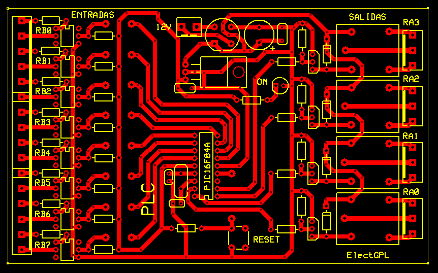
The PCB is as follows: NOTE must resize the size. This high resolution for better image quality.

0 comments:
Post a Comment