This circuit is in experimental stage, of course work but has not been tested yet.
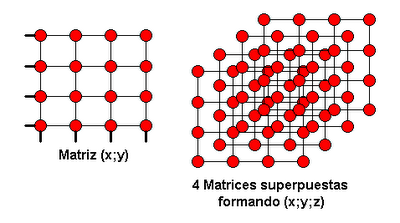
The operation is simple. for a 4x4x4 cube of LEDs, it requires 4 4x4 matrices thus overlapping the 3 dimensions are achieved.
The interface is of type (x, y, z) but in binary, the 00 bone represents 0, 01 represents 1, 10 represents 2 and 11 represents 3. this is for all three dimensions, so that with only 6 bits of data we manage natural coordinates cubic matrix.
The circuit consists of 5 integrated software. 74LS244
2-2-1-74LS14 74LS139
TTL logic because it can only feed to 5Vdc, analyzing the first array of four, we note that we require to operate (x, y) of the same, so we use 1 / 2 of the 74LS139 which is a binary to decimal decoder, therefore according to the code entered on your entry send us a logical 1 to the corresponding output, such as 2 bit input are only 4 outputs. Having already
value "and" we need the "x" which is given by 2 / 2 of the 74LS139 and through this to the 1 / 2 of which are buffer 74LS244 Tri-State, are used to discriminate between the 4 matrices, ie when we give a value of (x, y) will arrive at 4 matrices but we lack the component "z" in this case will enable the 74LS244 as appropriate.
as the third decoder, the axis "z", controls the enabling of each 1 / 2 74LS244 and thus control which we light array of the four. With these integrated
74LS139 and 74LS244, we access the three-dimensional coordinates.
The last is the 74LS14 integrated which is a hex-Schmitt Trigger, this chip's main function is to invert the first input bit decoder, since the array needs to forward and reverse polarized light to achieve a point in the same .
Then leave two graphs, the first is to be mounted as four overlapping matrices, each a red dot LED.
and the second image is the same circuit.


0 comments:
Post a Comment