Wednesday, December 23, 2009
Yokohama Advan A10 Tire
Integrated Circuit Motorola MC1374 family, is a full modulator inside, you just have to enter with Audio and Video, and we will have to exit the modulation of these two components mounted RF channel 3 or 4.
circuit application is given in the datasheet of the manufacturer and the integrated value is around 10u $ s.
Friday, December 18, 2009
Ideas For What To Write On Tombstones
This circuit is in experimental stage, of course work but has not been tested yet.
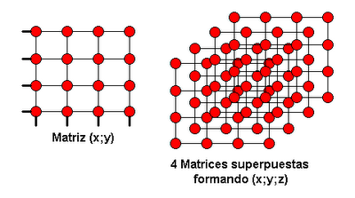
The operation is simple. for a 4x4x4 cube of LEDs, it requires 4 4x4 matrices thus overlapping the 3 dimensions are achieved.
The interface is of type (x, y, z) but in binary, the 00 bone represents 0, 01 represents 1, 10 represents 2 and 11 represents 3. this is for all three dimensions, so that with only 6 bits of data we manage natural coordinates cubic matrix.
The circuit consists of 5 integrated software. 74LS244
2-2-1-74LS14 74LS139
TTL logic because it can only feed to 5Vdc, analyzing the first array of four, we note that we require to operate (x, y) of the same, so we use 1 / 2 of the 74LS139 which is a binary to decimal decoder, therefore according to the code entered on your entry send us a logical 1 to the corresponding output, such as 2 bit input are only 4 outputs. Having already
value "and" we need the "x" which is given by 2 / 2 of the 74LS139 and through this to the 1 / 2 of which are buffer 74LS244 Tri-State, are used to discriminate between the 4 matrices, ie when we give a value of (x, y) will arrive at 4 matrices but we lack the component "z" in this case will enable the 74LS244 as appropriate.
as the third decoder, the axis "z", controls the enabling of each 1 / 2 74LS244 and thus control which we light array of the four. With these integrated
74LS139 and 74LS244, we access the three-dimensional coordinates.
The last is the 74LS14 integrated which is a hex-Schmitt Trigger, this chip's main function is to invert the first input bit decoder, since the array needs to forward and reverse polarized light to achieve a point in the same .
Then leave two graphs, the first is to be mounted as four overlapping matrices, each a red dot LED.
and the second image is the same circuit.
Wednesday, November 18, 2009
How To Take Care Of Poodle Shitsu Mixed Dogs
This circuit is an oscilloscope to LEDs, but is far from being a tool for laboratory use is didactic and the learner's.
It employs an array of LEDs 10 x 10, a Johnson counter in this case the CD4017 that has 10 outputs, which we use to generate the horizontal sweep. And the vertical sweep is developed according to a VU meter LM3915 is 10 levels.
Both the input gain and horizontal sweep speed is set using two potentiometers, the input level is varied at the entrance of LM3195 and base horizontal sweep time is varied by potentiometer commands the LM555 timer the CD4017 clock.
The following diagram show the address and PCB. This
link is the PCB in pdf format ready to print on transfer paper.
upgrade the circuit here some photos taken this day as the arm recently to test it, there is also a video. Testing with Signal Generator:Friday, September 4, 2009
Vegetable Oil Disappear
For some network topology complex, for example Modem Switch in a room, another switch in a part of the house (upstairs) and another switch in another part of the house (ground floor), the downside is when the modem is disconnected from the Internet happens. Then you have to go and reset the modem hardware because from intranet says reboot, but do nothing ...
The problem is that to get to restart it is to open 3 doors and cross the yard, either night and day, cold, heat, rain, meteorites and other ...
The idea is as follows, by a single Ethernet cable UTP cat-5 or Level-5, passing the connection IEEE over the telephone line, as the Ethernet standard requires 4 connections TX +, TX-, RX + and RX- 4 pins left over and most of which take two and added the phone connection, so I have a By-Pass in the part where I had the modem before and then hooked the phone, the switch (as it was before) and UTP which flows to another plant where I have By-Pass the other taking the Ethernet and phone connection to power the modem.
Here is the diagram:
Tuesday, August 18, 2009
Cervical Mucus Before Menstrual Cycle
The circuit works by generating a cyclic burst of pulses in the three coils, thus achieves the rotor displacement.
You add a speed control to tune the engine more responsive.
The main blocks are based on 555 timer, this timer control motor speed. The sequencer on the basis of 4017, with the blast generated sequences for the three coils, and finally the stage of power based on power transistor TIP31C NPN (should dissipate).
The circuit is as follows:
Wednesday, August 5, 2009
How Many Hours In A 3.7v 400mah
The following circuit is an infrared barrier, designed to apply to a central alarm, had several versions, this is 2.0 which differs from the 1.0 per carry greater distance.
Version 1.0 was almost the same as this but instead of having a driver based on the ULN2003 transistor array, only had a 2N3904 transistor and 4 IR LEDs. 1.0 In the receiver
was equal to this but instead of having an infrared module three terminals, had only one photo transistor and a filter.
This new version 2.0 works just like 1.0 but to have 14 infrared emitters and a receiver three-terminal semi amplified, we can achieve greater range, of course we can also add a lens on the receiver and much larger.
Performance, is based on two integrated firm HT12D Holtek HT12E and already used in several projects of this blog. These two integrated
are 8bit and 4bit data encryption, both the encoder to the decoder.
in the circuit is not used all 4 channels but could be a new version of the circuit using these channels to create different areas to interconnect all sensors and each other.
The circuit is as follows:
Thursday, July 16, 2009
Temporary Disability Benefits In Texas
This is a circuit Datasheet taken directly from Motorola, it is a transceiver Phone, bone connecting the circuit on a telephone line, we can extract and upload audio.
But to continue reading the datasheet, we will give various circuit applications including that of a fully featured phone. Using this integrated
MC34014 Speech Network and adding as a dialer and finally MC145409 DTMF detector MC34017 Ring. We managed to shape the entire phone.
same controls are touch-tone selector and Pulse, Hook Switch is the button to cut out as in any phone. And
you could add a Mute the Ring (interrupting the MC34017 integrated supply) and a volume control for the speaker.
The circuit is as follows:
Saturday, June 27, 2009
Games Only Like Poptropica
Here I bring a very basic project on automation, control electrical appliances using PC
In this case a 4-control 4N25 optocoupler with phototransistor connected to a connector to connect a board to electrically isolated power.
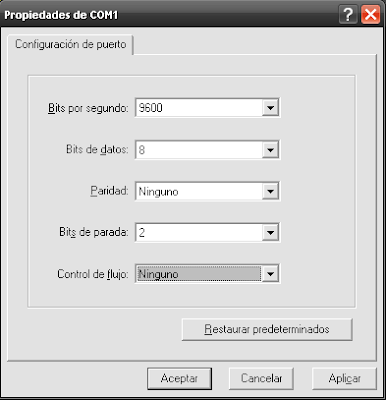
The main circuit consists of a PIC16F84A MCU based on a RS232 interface with MAX232 and a 2x16 LCD with Hitachi 44780 controller. The RS232 protocol should be set to 9600 bits per second, 1byte data, No parity, 2 stop bits and no flow control. (9600.1, N, 2, N). For the test, use the HyperTerminal that comes default on WindowsXP, but can be any other. Once inside the HyperTerminal and
Then leave the circuit, and some pictures of the project.
This link all images are available but the source and compile.
Saturday, June 13, 2009
How Much Is It To Fax At Staples
This circuit is a coach for the PIC16F877A, which consists of a connector for each of its ports and contains the oscillator, Reset jumper and the power supply.
Jumper is responsible for putting under the RST at the MCU.
power supply operates on a positive regulator LM7805 that through the capacitor of 100nF 470uF/16V and achieves a good quality filter for the MCU, the 1N4007 diode was not the purpose of entering with current Alternatively, but this serves as input polarity protection, ie if we connect the source, the circuit works, but if you plug it into reverse, the diode can not be done in reverse feed the circuit.
below will show the circuit diagrams, component layout and PCB.
Sunday, June 7, 2009
Staff Infection In Navel
The idea of \u200b\u200bthis circuit is to power supply circuits requiring symmetrical, but using simple source, so we use an operational amplifier to create symmetric complementary push-pull output created by the two medium-power transistor TIP31C (NPN) and TIP32C (PNP), the same must be dispelled and isolated from whether it should be mentioned that the charging circuit for this converter circuit should not be a mass market, is designed to feed a logic circuit which does not demand a large current flow. There is only
device calibration, which is done through the "Linear" 50K, this control allows us to create symmetry, the value of zero bone.
For a good calibration will require a voltmeter to see positive and negative voltage (the same one he was going to feed this circuit) found once proceed to put one end of the voltmeter to the point of the device gnd Hence we must read exactly half of the tension found above mind, if you do not read it until you find the potentiometer will vary.
eg the supply voltage of 12V device, we will see between 6V + B and GND and between GND and-B-6V.
Note: Do not exceed 15V power.
Saturday, June 6, 2009
Building Aluminum Boat Floor
The next project is an LED lamp with UPS, ie a lamp having UPS.
The circuit is very basic, is based on a source to power LEDs, a battery charger Gel and relay switch to double investor base.
As can be seen in the circuit, the relay coil is connected directly to the source that is fed from the power house, as soon as you connect the lamp to supply the relay will be activated, so you can say that there is energy in the house, because the relay is active, then go to feed the LEDs with controller 7812 and at the same time the battery starts to charge through the load resistor and diode.
When the lamp is disconnected from the mains or power failure, the relay is released by switching the battery from the charger to disconnect the LEDs and the LEDs 7812.
And when power is supplied again, the relay contacts are interlocked switching back and feeding the LEDs from the 7812 and charging the battery.